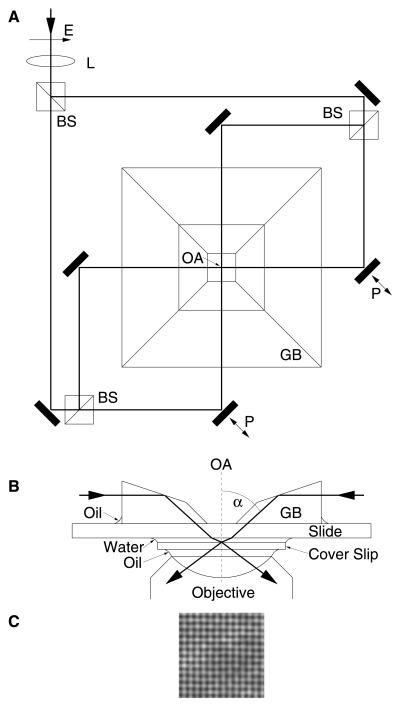
Figure 1.
Interference-generating apparatus (A and B) and measured intensity distribution (C). (A) Top view. A collimated laser beam (λ = 488 nm) with a diameter of 1.5 mm is slightly focused by a weak lens (L; focal length 300 mm) before being split by beam splitters (BS) into four beams of equal intensity that cross at the optical axis (OA) of the microscope. The position of L is adjusted for a beam diameter of about 120 μm in the object plane. With this configuration, the curvature of the wavefronts is negligible in the small field of view (about 25 μm × 25 μm). Piezo actuated mirrors (P) are used to vary the path length for two beams. E, electrical polarization. (B) Cut view through the optical axis. The four laser beams (only two are shown) are coupled to the object by a glass block (GB) which is oil-immersed to the slide. A standard fluorescence filter cube (not shown; emission, bandpass 515–565 nm; beam splitter, dichroic long-pass 510 nm) turned out to be sufficiently selective to avoid problems linked to residual laser light on the CCD chip even though the intensity of the captured laser light was several orders of magnitude higher than that of the fluorescence light. (C) The interference pattern recorded with the fluorescence filter removed from the imaging path of the microscope. An additional neutral density filter with an attenuation rate of 10−3 is used to protect the eyes as well as the camera against the high intensities of the direct laser light. The nodal spacing is about 200 nm.

