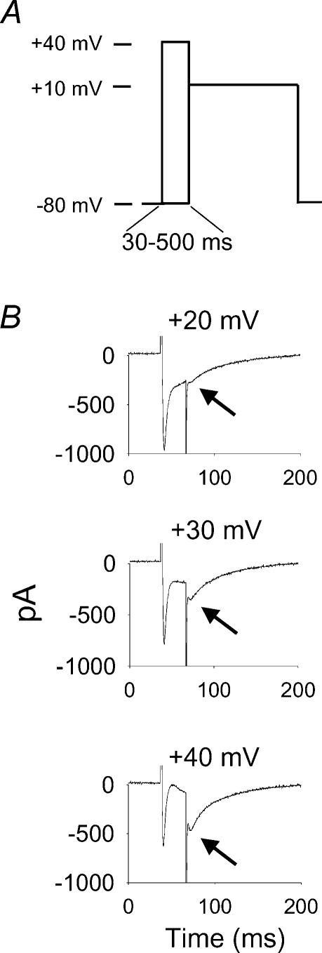
Figure 1. Non-steady-state inactivation voltage clamp protocol reveals increases in relative L-type Ca2+ current (ICa−L) after brief, positive conditioning steps.
A, a schematic representation of the voltage clamp protocol used for this study. Peak ICa−L was measured at a +10 mV test pulse, after conditioning steps from –80 to +40 mV in 10 mV steps, lasting from 30 to 500 ms. B, conditioning steps (30 ms) from +20 to +40 mV progressively increase available ICa−L at the test pulse of +10 mV (indicated by arrows). The conditioning prepulse potential is labelled above each panel. A transient outward Ca2+-activated Cl− current is superimposed on ICa−L during some conditioning steps positive to +10 mV (see Methods for details) (Wu et al. 1999b).

