
Figure 5.
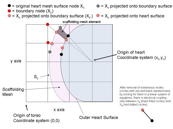
Creating the scaffolding mesh. The boundary nodes (Xb) are projected onto both the heart surface and the boundary surface, as indicated by the red diagonal line circles and red dotted circles, respectively. The original heart surface nodes are projected on to the boundary surface (black diagonal lined circle). The projected nodes along with the original heart surface node define an element of the scaffolding mesh (shown in black dotted fill for just one element).