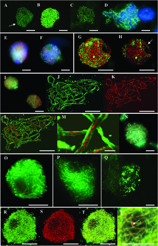
Figure 3.—
Projections of optical sections through PMCs of wild type showing immunolocalization of Asy1 protein at (A) leptotene (bouquet indicated by arrow), (B) zygotene, and (C) pachytene. (D) A conventional fluorescence image of Asy1 protein at diakinesis with dual immunolocalization and conventional fluorescence imaging of anti-Asy1 (red) and anti-Zyp1N (green) antibodies in wild type at (E) leptotene and (F) zygotene. (G) Projection of optical sections through a PMC of wild type showing dual immunolocalization of anti-Asy1 (red) and anti-Zyp1C (green) antibodies. (H) Single section from the optical stack used in G, confirming both the stage (pairing fork indicated by arrow) and the physical separation of linear tracts of the two proteins. (I) Conventional fluorescence image of late zygotene in wild type, showing virtually complete colocalization of Asy1 (red) and Zyp1 (green) proteins. Projection of optical sections through a PMC at pachytene of wild type, showing dual immunolocalization of antibodies to Asy1 protein (J), Zyp1C protein (K), and merged channels (L). (M) Detail from L showing that the Zyp1 signal is clearly sandwiched between Asy1 at this stage. (N) Conventional fluorescence image showing that Asy1 and Zyp1 proteins adopt spiral conformations at diplotene in wild type. Immunolocalization of Asy1 protein (green) in the sy10 mutant at stages equivalent to zygotene (O), pachytene (P), and diakinesis (Q). Projection of optical sections through a PMC at midprophase in the sy10 mutant, showing dual immunolocalization of antibodies to Zyp1N (green), Asy1 (red), merged channels (T), and detail showing coaligned linear signals of the two proteins (arrow in U). Bars, 10 μm, except that of M, which represents 1 μm.

