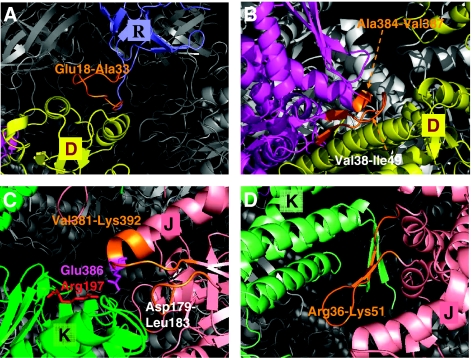
Figure 4.
A closer view of intra- and inter-subunit couplings at the interface of the clusters. Results are shown for the representative chains D (yellow) and E (magenta) on cis ring, J (pink) and K (green) on trans ring and R (blue) on GroES. The chain segments that establish the communication between clusters are colored orange. (A) Residues Glu18–Ala33 in the mobile loop (orange) of GroES chain R integrated into the cluster centered at the A-domain of chain D establish the communication between cis ring and co-chaperonin. (B) Positive intra-ring cooperativity imparted by the coupling of chain E residues, Val38–Ile49 and Ala384-Val387 shown in orange, into cluster 18 dominated by chain D. (C) Inter-subunit couplings at trans ring A-domains. Cluster 32 embodies the A-domain of chain K, but also captures a few residues (Val381–Lys392, Asp179–Leu183; shown in orange) from chain J. (D) Cluster 25 is centered on the E-domain of chain K on trans ring. Note that this cluster engages E1 residues Arg36–Lys51 from chain J. Negative cooperativity between the two rings can be compared by comparing panels B and D, both corresponding to the E-domains of the respective cis and trans rings. The residues serving as messengers (orange) between the subunits belong to either clockwise (panel B) or counterclockwise (panel D) neighbors, as viewed from the cap, that is, the two rings have opposite rotational direction of inter-subunit couplings. The distribution of different chain residues in the examined representative clusters is listed in Table I.

