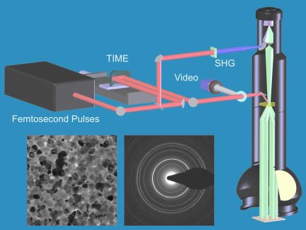
Fig. 1.
A schematic of UEM at California Institute of Technology. Shown are the femtosecond laser system and the transmission electron column. The temporal resolution is determined by the time between the single-electron packets and the initiating heat or excitation pulses. Typical images (real space) and diffraction patterns obtained by UEM are also show (for details see the text).

