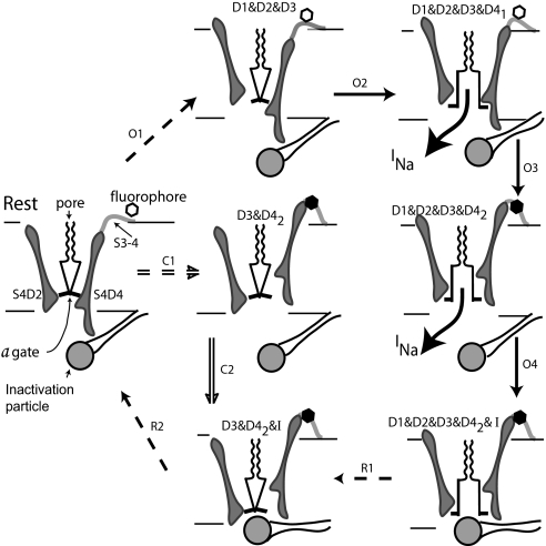
Fig. 6.
Channel activation and inactivation. At rest, the S4s of all domains are fully deactivated, forced inward by negative Vm. This pinches closed the a gate at the inner end of the pore. The scallops represent the selectivity filter. Path O: On depolarizing to 0 mV, the most likely path is shown by arrows O1–O4, with dashed arrows indicating multiple steps. Conduction begins when all four domains are activated, with D4 activated to stage 1. Stage 2 activation of D4 removes the steric hindrance that prevents closing of the inactivation gate and quenches fluorescence of the tag attached to the S3–4 linker of D4. Path C: At −30 mV, paths C and O are equally probable. After step C1, the a gate is held closed by D1 and D2, which are not activated, but inactivation is possible because D3 and D4 are activated, the latter to stage 2. The inactivation gate closes in step C2. Recovery: Steps R1 close the a gate as D1 and D2 deactivate, generating the inactivation resistant component of Ig. During step R2, negative Vm drives the S4s of D3 and D4 inward, the latter forcing the inactivation particle out of blocking position.

