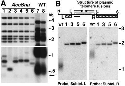
Figure 4.
Formation of telomere fusions after introduction of a linear plasmid. (A) A Southern blot hybridized with a telomeric probe of EcoRI-digested DNA isolated from the first streak after cells were transformed with the K. lactis linear plasmid pHisLin1. The lower part of the gel is shown more darkly exposed. Both telomeres of the linear plasmid run at the same position (≈0.5 kb) in wild-type TER1 cells (lanes 7 and 8). Six independent small colony transformants of pHisLin1 into ter1-AccSna are shown in lanes 1–6. Arrow indicates the position of short, unfused telomeres visible in some of the ter1-AccSna transformants. (B) Southern blots of ApaLI + NgoMIV-digested DNA from some of the same clones after five serial restreaks hybridized with probes unique to either the left or the right subtelomeric region of the transformed linear vector. Numbers above lanes match clone designations from A. Diagram above shows the inferred map of a typical telomere fusion. White and gray boxes indicate wild-type and mutant telomeric repeats, respectively. Arrows indicate the direction of the telomeric ends before fusion. Hatched boxes indicate regions used as probes and black bar indicates 200 bp. N, E, and A indicate NgoMIV, EcoRI, and ApaLI restriction sites.

