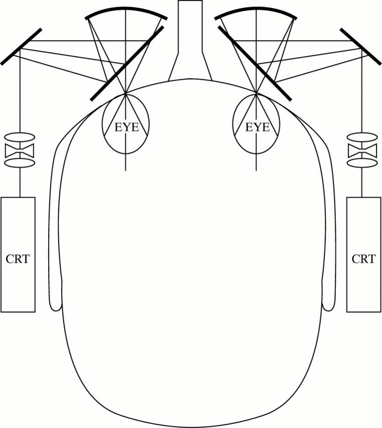
Figure 1 .

Schematic diagram of the LVIS. A magnified intermediate image of each cathode ray tube (CRT) screen is formed by an aspheric triplet lens system. Light from the temple arm CRT is directed by the folding mirrors to the 50/50 beam splitter in front of the eye. The curved mirror images the exit pupil of the optical system in the plane of the subject's pupil and displays a 50° × 40° image of the CRT screen. A refractive correction, if necessary, can be inserted between the CRT and the aspheric triplet (redrawn after Massof et al 15).
