Figure 5.
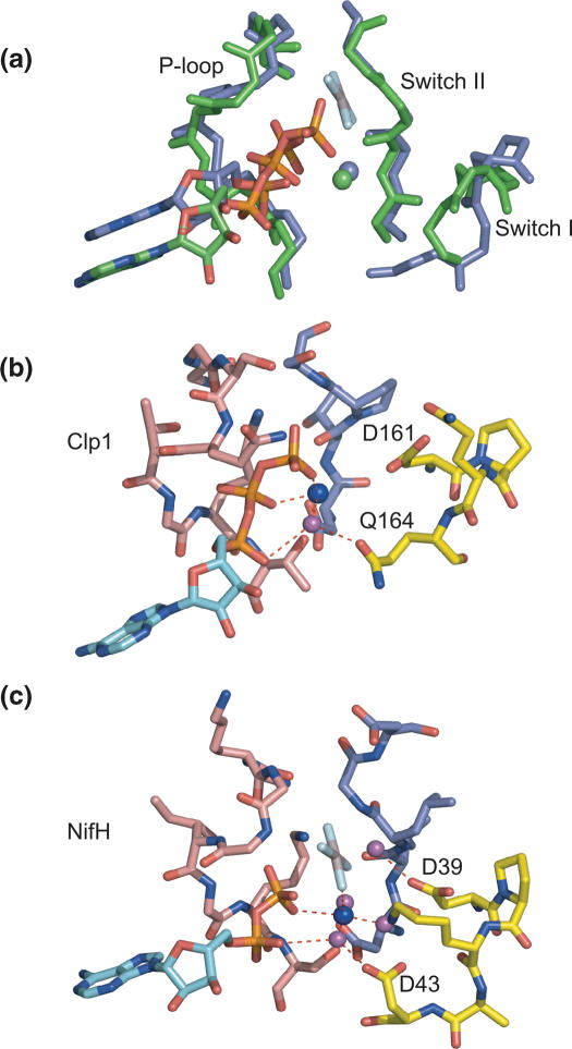
The switch loops and Mg2+ co-ordination. (a) An overlap of the Clp1-ATP (green) and NifH-AlF4 (blue) structures around the P-loop, Switch I and switch II nucleotide binding regions. The backbone representation for each molecule is shown together with a stick representation for the ATP or ADP-AlF4. (b) Interactions of the magnesium ion with the switch loops of Clp1. Stick representations of the P-loop, Switch I and Switch II are shown in light red, yellow and blue, respectively. The adenine base of the ATP is shown in cyan and the magnesium ion is shown as a blue sphere. The water molecule co-ordinated by the magnesium ion and hydrogen bonded by the side-chain of Q164 together with α phosphate oxygen is shown as a magenta sphere. D161 in Switch I is also indicated. (c) Interactions of the magnesium ion with the switch loops of NifH-ADP-AlF4. The colouring scheme is the same as in (B). D43 and D39 are indicated.

