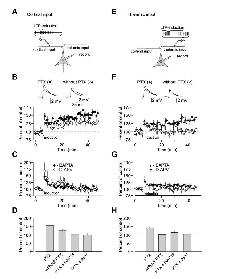
Figure 1.
Properties of Spike Timing-Dependent LTP at the Cortico-Amygdala and Thalamo-Amygdala Synapses. (A) A schematic representation of the experimental design when cortical input was individually activated, showing the position of the recording and stimulation electrodes. (B) Summary graphs of the LTP experiments in cortical input in the presence of PTX (100 μM, mean ±SEM; n = 12) and without PTX (n = 9) in the bath solution. To induce LTP, 80 EPSPs were evoked at a frequency of 2 Hz; each EPSP was paired with action potential induced in a recorded neuron with 4-8 ms delay from the onset of the EPSP by short depolarizing current injections through the recording electrode. Insets show the average of 10 EPSPs recorded in individual experiments before and 35 min after the LTP-inducing stimulation (arrow) with PTX (left) or without PTX (right) in the bath solution. (C) LTP in cortical input is blocked by D-APV (50 μM, n = 4) in the external solution or when a high concentration of Ca2+ chelator BAPTA (10mM) is included in the recording pipette solution (n = 4). (D) Summary of LTP experiments (mean ±SEM) at cortico-amygdala synapses. (E) A schematic representation of the experimental design in thalamic pathway. (F) Summary graphs of the LTP experiments in thalamic input in the presence of PTX (n = 6) and without PTX (n = 5) in the bath solution. Insets show the average of 10 thalamo-amygdala EPSPs recorded in individual experiments before and 35 min after the LTP-inducing stimulation with PTX (left) or without PTX (right) in the bath solution. (G) LTP in thalamic input is blocked by D-APV (50 μM, n = 6) in the bath solution or by BAPTA (10mM) in the recording pipette solution (n = 10). (H) Summary of LTP experiments (mean ±SEM) at thalamo-amygdala synapses.

