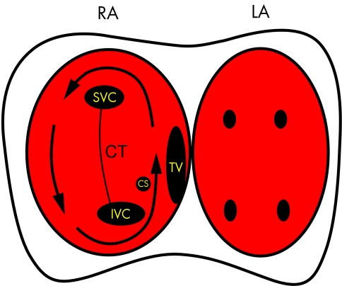
Figure 4.
Diagram showing the pathway taken by the re-entry wavefront causing atrial flutter (arrow). The right (RA) and left atria (LA) are depicted with the anatomical landmarks in the right atria marked as follows: SVC, superior vena cava; IVC, inferior vena cava; CS, coronary sinus os; TV, tricuspid valve; CT, crista terminalis. The TV and CT form lines of conduction block which “electrically” divide the atria into two halves. The only electrical connections between these two halves are the roof and appendage of the right atrium and the isthmus between the TV and IVC. Note that the narrowest part of the re-entry circuit is this isthmus which is why this is the target for ablation of atrial flutter. The left atrium activates via conduction through the septum but is not part of the re-entry circuit.

