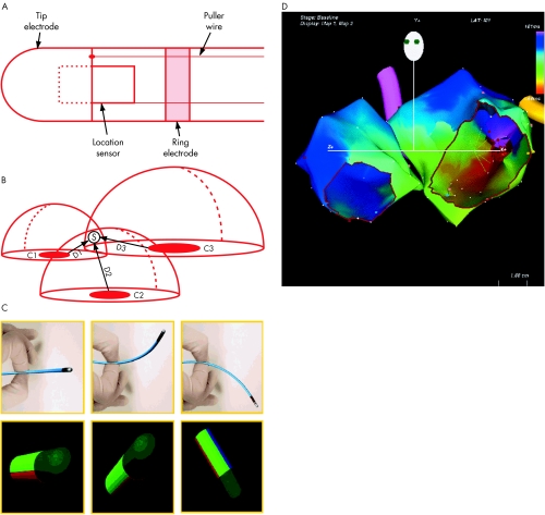
Figure 1.
Electroanatomic mapping. (A) The catheter is composed of tip and ring electrodes and a location sensor embedded within the catheter. (B) A location pad with three coils (C1, C2, and C3) generates magnetic fields that decay as a function of distance from the coils. The sensor measures the strength of each field, permitting determination of the distance from each coil (D1, D2, D3). The intersection of three theoretical spheres of radii D1, D2, and D3 determines the catheter tip location in space. Reproduced from Gepstein et al,20 with permission. (C) Deflection of the catheter in space (top panels) results in real time display of catheter orientation on the computer screen, to guide non-fluoroscopic manipulation. (D) Activation map from a patient with left atrial figure of eight re-entrant tachycardia. The two atria are shown in the left anterior oblique view, with tricuspid valve and mitral valve cut out. The colour at each anatomic point shows local activation time relative to the reference catheter (scale top right).

