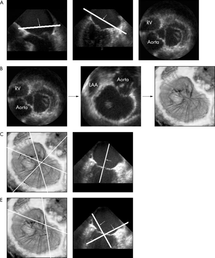
Figure 1.

(A) Cut planes are made in the orthogonal four and two chamber two dimensional (2D) views parallel to the plane of the mitral annulus, allowing 2D visualisation of the valve from above. (B) This image is rotated to represent the surgeon’s eye view and magnified to optimise the depiction of the mitral valve. This is volume rendered to a three dimensional (3D) image. (C) Three cut planes are made through A1/P1, A2/P2, and A3/P3 as shown. Keeping the perpendicular plane along the long axis of the ventricle, corresponding longitudinal images are then surface rendered to show the valve leaflets optimally. (D) The commissural zones are visualised similarly but with an oblique plane looking down onto the valve from the atrium. A1/P1, lateral scallops of anterior and posterior mitral leaflets; A2/P2, middle scallops of anterior and posterior leaflets; A3/P3, medial scallops of anterior and posterior leaflets; LAA, left atrial appendage; RV, right ventricle.
