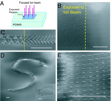
Fig. 1.
Wrinkle patterns on PDMS surface induced by FIB irradiation. (A) Selected surface areas of the PDMS are exposed to FIB as shown schematically. (B) The wrinkles appear only on the areas of the PDMS exposed to FIB. The SEM picture shows the boundary of a 200 × 200-μm region exposed to FIB with the fluence of ≈1013 ions per cm2 in a single scan mode. The wrinkles on the exposed area are 1D with the wavelength of ≈460 nm, while the unexposed surface remains flat. (C) The morphology of the wrinkled skin depends on the ion fluence, which can be controlled by varying the relative velocity of the substrate and the beam. The SEM image shows a wrinkled pattern generated along a straight path with width of 4.0 μm with two different ion fluences: 1.8 × 10¹⁴ (Right) and 9 × 10¹⁵ (Left) ions per cm2. The surface of the PDMS outside this path remains flat. (D) The wrinkle pattern can be generated along selected paths with specified width by controlling the relative motion of the substrate and ion beam. Here the pattern follows an S-shaped path with a width of 6 μm, created at a constant ion fluence, 5.0 × 10¹⁵ ions per cm2. Inset shows a circular path with the same width created at the same ion fluence. (E) Islands of buckled stiff skins on the PDMS created by controlling the ion beam spot diameter and ion beam spot spacing. Each island has the diameter of ≈500 nm and is a smooth buckle with peak height of ≈35 nm. The spacing between the islands is ≈1.5 μm. The applied ion fluence (averaged over the whole area of the PDMS) is 7 × 10¹² ions per cm2. (Scale bars: 10 μm.)

