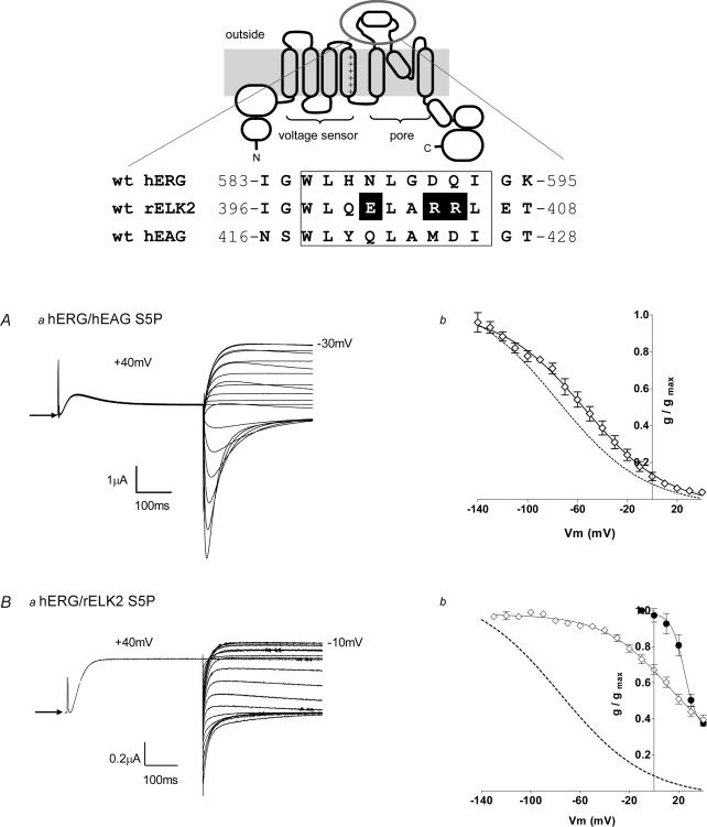
Figure 2. EAG family S5P chimaera characteristics.
Upper panel, alignment of the residues of the S5P linker of hERG, rELK2 and hEAG is shown at the top of the figure below a cartoon depicting wt hERG structure. The demonstrated α-helical region (Torres et al. 2003) is boxed. The charged residues of interest within the α-helical region of rELK2 are highlighted. Aa, steady-state inactivation of hERG/hEAG S5P chimaera. Typical example of currents recorded from hERG/hEAG S5P channels during a steady-state inactivation voltage protocol (see Fig. 1A) are shown. Arrow indicates zero current. Ab, the conductance–voltage plot of hERG/hEAG S5P (•). The curve fitted to the hERG/hEAG S5P data is a Boltzmann function with a V0.5 of inactivation of −57 mV and a slope factor of −31 mV (n = 5). The dotted line shows the Boltzmann fit to the wt hERG data from Fig. 1B. Ba, typical example of currents recorded from hERG/rELK2 S5P chimaera channels during a steady-state inactivation voltage protocol (see Fig. 1A). Arrow indicates zero current. Bb, the conductance–voltage plot of hERG/rELK2 S5P (•) compared with wt hERG (dotted line) and wt rELK2 (•). The curve fitted to the hERG/rELK2 S5P data is a Boltzmann function with a V0.5 of inactivation of 27 mV and a slope factor of −34 mV (n = 4). The data for wt hERG and wt rELK2 are reproduced from Fig. 1B.

