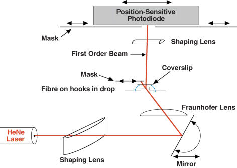
Figure 1. Diagram of laser diffractometer.
The beam from a 5-mW HeNe laser was passed through a shaping lens and Fraunhofer lens (see Methods) via an adjustable mirror that controlled the angle of incidence onto the fibre. The fibre was held in a small drop of solution (40 μl) between a cooled glass pedestal and a glass coverslip by hooks attached to the servomotor and force transducer (not shown). The zeroth-order beam was blocked by a movable mask, while the first-order beam was passed to the photodiode. A shaping lens focused the first-order line down to a spot at the photodiode. Scattered light and lines of higher orders (on the same side as the measured first-order line) were blocked by masks at the photodiode. The fibre was positioned 31 cm from the photodiode and 12.2 cm from the mirror at the position illuminated by the laser (distances orthogonal to fibre axis). Drawing not to scale.

