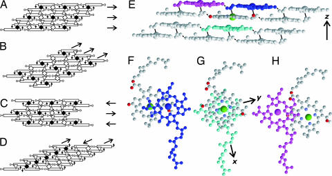
Fig. 4.
BChl c assembly models satisfying head–head, head–tail, and tail–tail contacts and the structure of the BChl c assembly determined under 13C 13C distance constraints. (A) Parallel-dimer layers. (B) Uneven-dimer columns. (C) Antiparallel-dimer layers. (D) Antiparallel-monomer columns. Arrows in the structure indicate the coordination bonds between C31
 OH and Mg. Open rectangles represent BChl c rings.
  , ◇, and ▵ stand for the head–head, tail–tail, and head–tail contacts, respectively. The arrows on the right of A and C and those at the top of B and D indicate layers and columns, respectively. (E) A side view of the structure of the BChl c assembly. Solid and broken lines represent coordination and hydrogen bonds, respectively. Oxygen atoms are colored red. (F) A top view of the piggyback dimer. (G) A top view of the interdimer full stacking at the center of E. (H) A top view of the intercolumn contact between neighboring dimers. The coordinates of BChl c molecules are given in the legend to SI Fig. 7.

