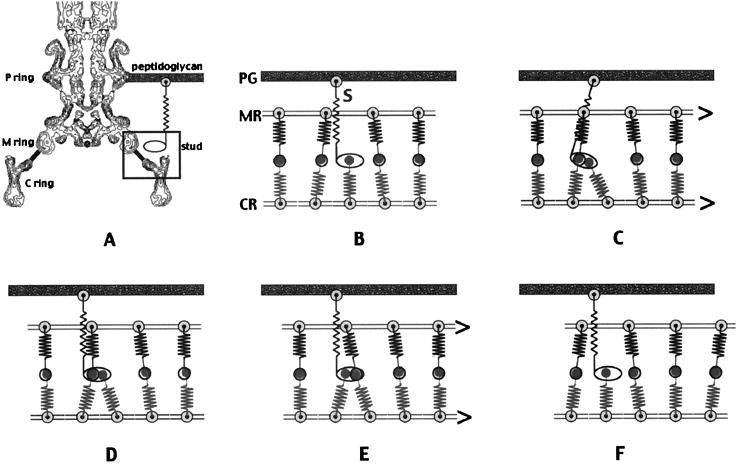
Figure 5.
Schematic of the model for the mechanism of motor rotation. (A) A contour plot of the density of the averaged image in Fig. 4A, except that the L and P rings and part of the hook are included. The stud and its connection to the peptidoglycan layer are shown in cartoon form. The stud is not attached to the C or M ring here, but it is in B. The bar connecting the C ring and the M ring is intended to represent the C ring levers and their binding sites on the M ring. The zig-zag lines here and in Fig. 3F depict possible elastic elements. The box indicates the part of the motor shown in cartoon form in B–F. (B) The model represents a short segment of the full motor. It shows five of the C ring (CR) subunits, four of the M (MR) ring subunits, and one stud (MotA–MotB complex). The difference in the number of subunits in the M and C rings in the model represents the differences in the number of subunits in these rings in the basal body. In particular, not all 34 levers from the C ring can mate with the bonding sites on the M ring, which has only 26 sites. The extra levers in our model form a complex with the MotA–MotB stud(s). In the model, we have shown only one extra lever, which is in a complex with a stud. We assume that all of the forces from the elastic elements are initially in balance. (C) The stud and unpaired C ring lever move, perhaps by Brownian motion, to the left and bind to the M ring–lever complex. On binding, the elastic elements generate a force, and the M and C rings move. (D) Motion stops when the forces are again balanced. (E) The unpaired lever from the C ring is now swapped so that it is bound to the M ring, and the stud and its new partner in the C ring are freed from the complex. Force is generated, and the M and C rings again move. (F) When the motion stops, the M ring and C ring have each moved by one subunit, and hence by different angles. The M ring has undergone 1/26 of a revolution, whereas the C ring has only undergone 1/34 of a revolution.

