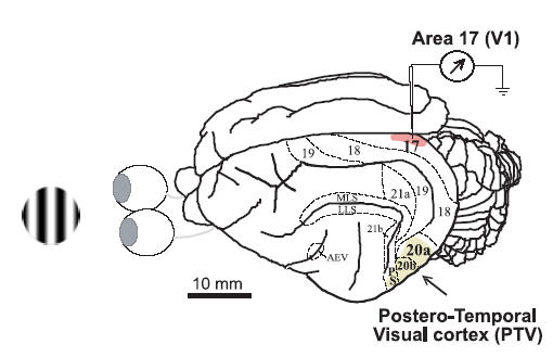
Figure 1. Location of recording sites and cortical inactivation site.

On the left is an example of a patch of sine-wave luminance-modulated drifting grating used as a visual stimulus. On the right is a dorsolateral view of the left cerebral hemisphere of the cat showing the locations of visual cortical areas. The locations of cytoarchitectonic and functional areas 17, 18, 19, 21a, 21b, 20a and 20b, as well as those of the anterior ectosylvian visual area (AEV), posterior suprasylvian area (PS) and several areas in the medial lateral suprasylvian (MLS) region and the lateral lateral suprasylvian (LLS) region are indicated (after Burke et al. 1998). The shaded part of area 17 (striate cortex, area V1) indicates the general location of all our electrode penetrations. The area labelled as ‘Postero-Temporal Visual cortex (PTV)’ represents the cortical surface that was in contact with the cooling probe.
