
Figure 10. Effect of voltage upswing on NaP.
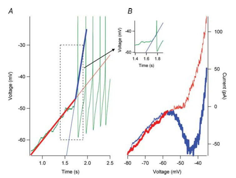
In the presence of 0.5 mm riluzole, repetitive firing (A, green trace) was observed in response to a depolarizing current ramp injection. In response to a voltage-clamp ramp command (A, red trace) that approximated the subthreshold rate of rise to the current ramp command, no negative slope region was observed in the I–V relation (B, red trace). However, prior to spike initiation, an upswing in the membrane potential (inset and Figure 7) was observed. (The inset shows the boxed region in A.) A voltage-clamp command that approximated this upswing (A, blue trace) generated a robust persistent inward current (B, blue trace). Therefore, during current-clamp conditions, the voltage transitions from the slow voltage command (A, bold red trace) to the fast voltage command (A, bold blue trace) when the voltage upswing begins. The current response to the voltages transitions from the bold red trace (B) to the bold blue trace (B) and the negative slope region to generate a spike is now present. The thin red lines (A and B) represent the slow voltage command and current response after the voltage upswing. The thin blue lines (A and B) represent the fast voltage command and current response before the voltage upswing.