
Figure 13.
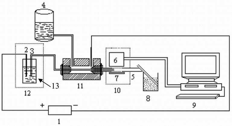
Schematic diagram of the capillary electrophoresis-chemiluminescence (CE -CL) system. (1) High-voltage power; (2) Pt electrode; (3) electrophoretic capillary; (4) CL solution reservoir; (5) reaction capillary; (6) photomultiplier tube (PMT); (7) reflection mirror; (8) waste-solution reservoir; (9) computer; (10) black box; (11) reaction tee; (12) glass cover; and, (13) buffer reservoir. [76]