
Figure 4.
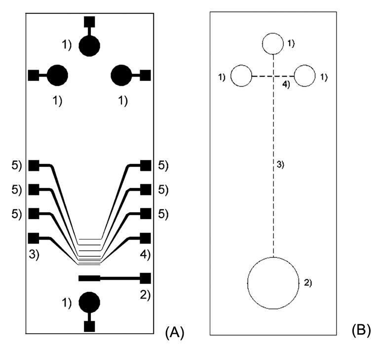
Schematic diagram of the glass chip (A) with: (1) high-voltage electrodes; (2) counter electrode; (3) reference electrode; (4) working electrode; and, (5) decoupler electrodes. Schematic diagram of the PDMS chip (B) with: (1) buffer and sample reservoirs; (2) waste and detection reservoir; (3) separation channel; and, (4) injection channel [25].