
Figure 9.
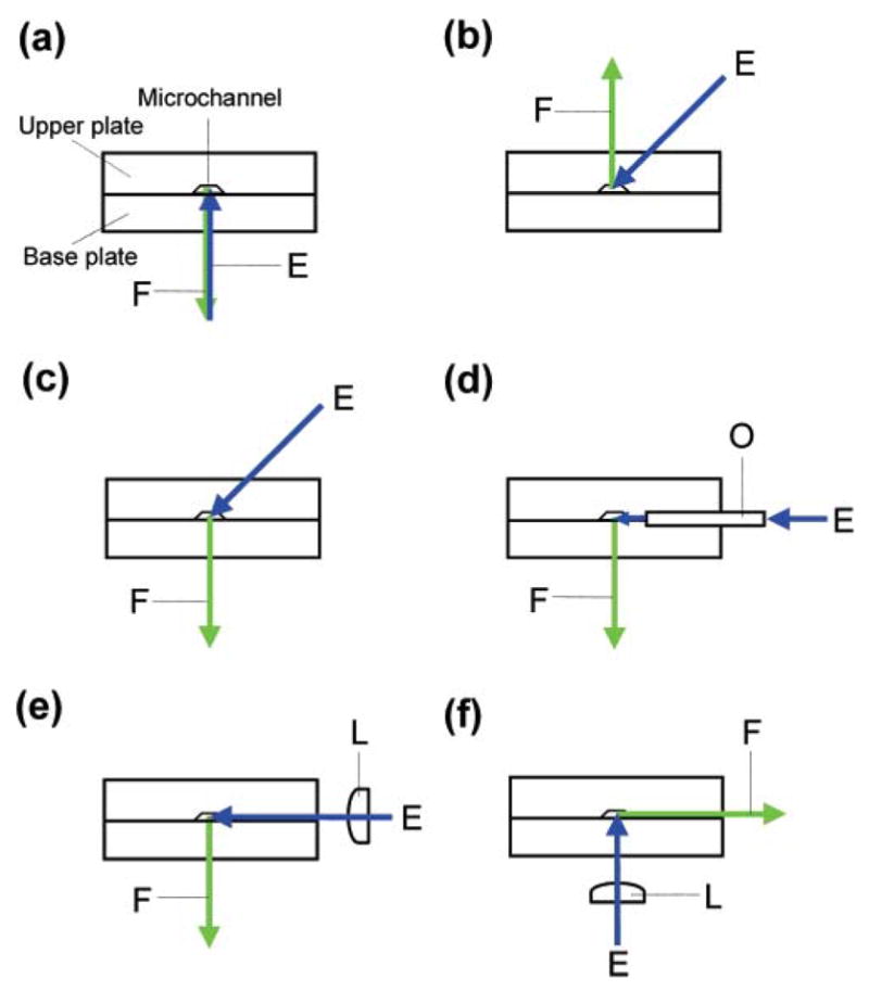
Schematic diagrams of typical optical arrangements of microfluidic chip laser-induced fluorescence (LIF) detection systems: E, excitation source; F, fluorescence; L, lens; O, optical fiber [53].
Official websites use .gov
A
.gov website belongs to an official
government organization in the United States.
Secure .gov websites use HTTPS
A lock (
) or https:// means you've safely
connected to the .gov website. Share sensitive
information only on official, secure websites.
Schematic diagrams of typical optical arrangements of microfluidic chip laser-induced fluorescence (LIF) detection systems: E, excitation source; F, fluorescence; L, lens; O, optical fiber [53].