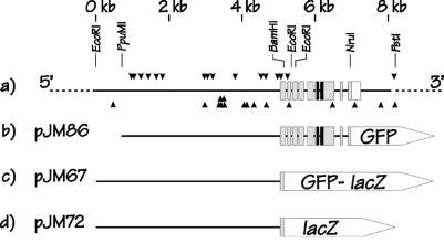
Figure 1.
Schematic representation of the C. elegans elt-2 gene and elt-2∷reporter constructs used in the present study. (a) The chromosomal region surrounding the C. elegans elt-2 gene near the middle of the X chromosome. Gray boxes represent exons; the black region represents the elt-2 DNA binding domain, i.e., the GATA-type zinc finger + 25 aa downstream; unfilled box represents the 3′ untranslated region. Coordinates are marked at the top as kbp downstream from an EcoRI site (≈5,100 bp upstream of the elt-2 ATG codon). Selected restriction enzyme cleavage sites used in the various constructs are shown. Arrowheads represent positions of potential elt-2 binding sites, i.e., WGATAR or YTATCW for down and up facing arrowheads, respectively. (b) Schematic representation of the plasmid pJM86, the main construct used in the present paper. pJM86 contains the coding sequences of GFP fused at the NruI site such that only the nine C-terminal amino acids of ELT-2 are removed. The full elt-2 DNA binding domain is included. The plasmid vector is pPD95.77 (c and d) Schematic representation of two control constructs, pJM67 and pJM72, in which either GFP/lacZ or lacZ reporters, respectively are fused to the elt-2 gene at the BamHI site, 32 aa downstream of the elt-2 ATG codon. The ELT-2 DNA binding domain is not included in either construct.

