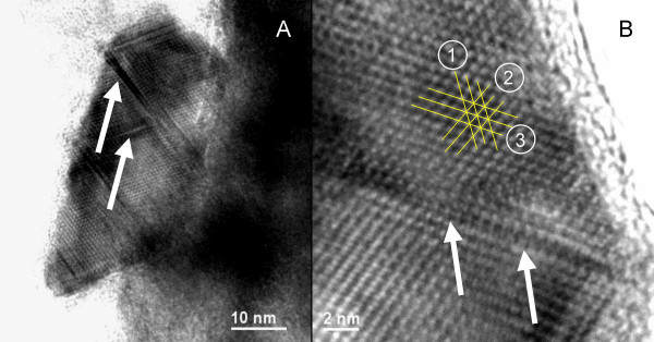
Figure 8.
Typical HRTEM picture of greigite formed at 200°C in the presence of 10 mol-% of zerovalent sulfur as polysulfide and quenched with liquid nitrogen to -196°C. (A) The overview shows defects inside the crystal along crystallographic planes (arrows). (B) Three sets of lattice fringes are marked in the close-up: Set 1 has a distance of 0.56 nm, set 2 and 3 have a distance of 0.50 nm. Set 2 forms angles of 70° and 55° with sets 3 and 1, respectively. The distances and angular separations of the crystallographic planes are consistent with a greigite crystal viewed along the [01-1] crystal axis. Lattice fringe sets 2 and 3 correspond to the {111} plane and set 1 corresponds to the {200} plane. White arrows highlight a crystal defect causing a slight mismatch between adjacent lattices.

