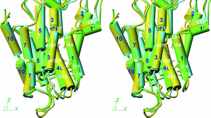
Fig. 6.
Differences in orientation of the transmembrane helices in three crystal structures. E2(CPA) (yellow), E2(TG+BHQ) (light green), and E2·MgF42− (cyan) are superimposed with the M7–M10 helices and are shown in stereo in the same direction as in Fig. 1. M2, M3, M5, and M7 are represented with two to three cylinders, although they are continuous helices. Some of the residues used in helix–helix contacts are shown.

