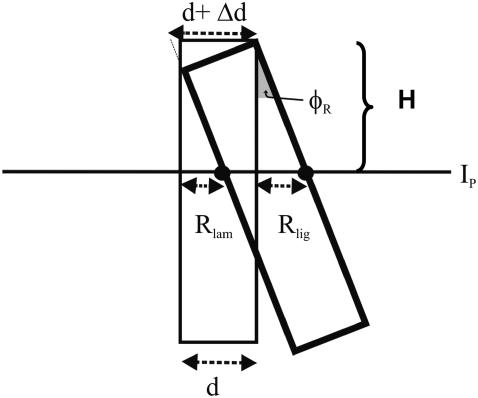
FIGURE 14.
Schematic drawing of an OHC radial cross section. The cell is shown at rest (thin line) and after it has rotated about the upper right edge (thick line). The angle of rotation (pivoting angle) is indicated by φR. d, diameter of cell; Δd, observed change in diameter of the cell due to pivoting; Rlig, radial displacement of the ligament-side edge of the cell; Rlam, radial displacement of the lamina-side edge of the cell.

