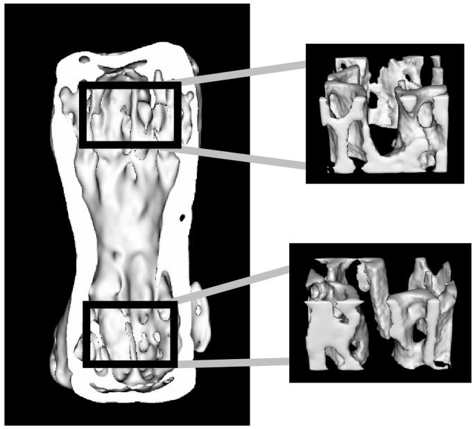
Figure 1.
Location of analysis regions for trabecular bone architecture.
Proximal and distal trabecular bone regions were obtained by fitting a box 15% of the specimen height in the axial direction and as large as possible in the anterior-posterior/medial-lateral plane, in the extreme ends of the trabecular cavity. Analyses of V-TB.N. and V-BV/TV were conducted separately for each region, then averaged to obtain one value for each specimen.

