FIGURE 8.
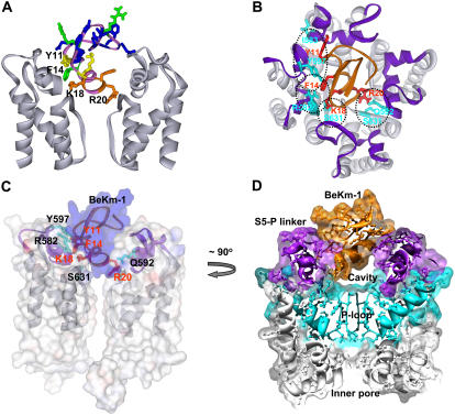
Docking of BeKm-1 in the outer mouth of hERG. (A) Side view of two hERG pore-forming domain subunits shown in gray. BeKm-1 (top center) is colored according to the effect of alanine substitution on the binding affinity (same color scheme as in Fig. 1 B). Residues K18, R20, F14, and Y11 are labeled. (B) View from the extracellular side toward the outer entrance of hERG pore-forming domain with BeKm-1 bound. Ribbons represent the backbones of channel and toxin. Color code: light gray = S5, P, and S6 segments, purple = S5-P linker, orange = BeKm-1. Residues that interact (based on the mutant cycle analysis) are shown in red for BeKm-1 and cyan for hERG. Specific pairwise interactions are encircled with dashed lines. The figure is the averaged structure during the second half of an MD simulation of the protein embedded in a POPE lipid bilayer. The exact fourfold symmetry of the starting model (before the MD simulations) is not maintained, and the helices of the S5-P linker became distorted in two subunits. (C and D) Side views of the same model using transparent surfaces to show the tight fit of the BeKm-1 toxin in the opening between the S5-P linkers (C) but a cavity between the toxin and the entrance to the selectivity filter (D). In panel C, only two of the hERG subunits are shown. The toxin surface is shown in blue, the channel surface shown in gray, and the ribbons for toxin and S5-P linkers shown in purple, with some of the interacting side chains shown as in panel B and labeled. The view in panel D represents an ∼90° clockwise rotation of the view in panel C around the central axis, with the following key elements labeled: BeKm-1 in orange, S5-P linkers in purple, P-loops in cyan, S5 and S6 segments in gray, and inner pore. Clipping planes were used to illustrate only a central cross section through all four subunits.

