
Figure 4.
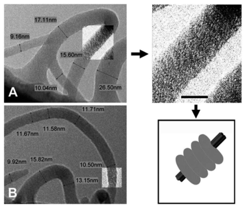
Electron microscopy of fluorescent PVP-coated SWNTs prepared at 0.2% SWNT/PVP ratio (0.4% SDS). (A) A Ψ-junction between thin bundles of PVP-FL-coated SWNTs. Arrow points to the expanded part of the image with increased contrast. Note tight stacking of the polymer coils. (Bar represents 10 nm.) This wrapping arrangement with tight coiling of PVP-FL around a small bundle of 8, 8 SWNTs is illustrated by the schematic on the right. (B) A Y-junction assembled from two individual coated nanotubes (seen at the lower left corner of the image). Note part of the image with increased contrast showing a “stack of pancakes” polymer coiling.