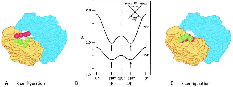
Figure 4.
Mutual arrangement of the tRNAs in the pre- and the post-translocational states. (A) Schematic representation of the R configuration in PRE by using the angle of 110°. (B) Dependence of the deviation Δ (Eq. 1) on the angle ψ between both tRNAs. The left half represents the R configuration, and the right half represents the S configuration (see also Insert). The minimal deviation is found at angles of ψ = 110° ± 10°. (C) Schematic representation of the S configuration in PRE by using the angle of 110°.

