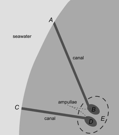
Figure 1. Simplified Schematic Depicting Two Ampullae within a Single Cluster, with Their Associated Canals and Pores.
Points A and C denote two pores, leading via gel-filled canals to their respective ampullae. Points B and D denote the inner ampullae, referencing electric potentials on the apical sides of the respective sensory epithelia. Point E is a common reference for the basal sides of ampullae within the cluster. The model used here emphasizes the potential differences arising along the internal gel of the narrow canals as driving the apical potentials, which lead to excitation or inhibition based on their relation to the relatively constant basal potential at point E (see text).

