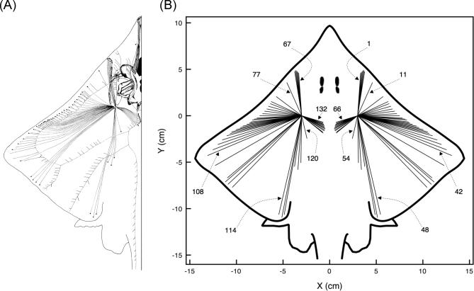
Figure 2. Canal Projections from the Dorsal Hyoid Ampullae of Raja laevis .
(A) Adapted from [14].
(B) As used in the present modeling work.
Here, ampullary clusters are treated as a single point for simplicity. (B) also presents the canal numbering used in plots in this study. The 132 dorsal hyoid canals in the barndoor skate morphology are numbered consecutively, with canals 1 to 66 in the right cluster, and canals 67 to 132 in the left cluster. As seen in the figure, the first canal in each cluster is the one pointing in the most forward direction, 4° off the longitudinal axis. The other canals in each cluster are numbered consecutively, clockwise for the right cluster, and counterclockwise for the left cluster. Locations of pores and ampullae used in modeling match those in the actual fish (A). In terms of potential differences between an ampulla and a pore for a given canal (which is what our model emphasizes), the physics of electromagnetism tells us that the actual shape of the canals is immaterial. Thus, we simply represent them as straight lines.

