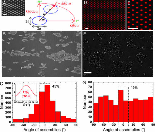
Fig. 1.
Epithelial cell growth on substrates with anisotropic rigidity. (A) Schematic representation of an anisotropic micropillar subjected to a force, F, where u⃗ is the displacement vector of the top of the pillar and θ is the direction of its deflection with respect to the longest semi-axis, a [i.e., the stiffest direction of the substrate (θ = 0°)]. The spring constant, k(θ), depends on the force orientation (see Eq. 1). (Inset) Scanning electron micrograph of an array of oval PDMS pillars. (Scale bar: 5 μm.) (B) MDCK cell islands grown on these substrates and visualized by optical microscopy. The horizontal direction corresponds to the polar axis, θ = 0°. (Image dimensions: length × height = 877 × 512 μm.) (C) Angular distribution of cell assemblies with respect to the stiffest direction (θ = 0°). The dashed rectangle indicates that 45% of the islands are elongated in a 30°-wide sector centered on θ = 0°. (Inset) Profile plot of the stiffness k(θ) for this experiment, computed from Eq. 1. (D) Fluorescence microscopy image of an array of oval patches of Cy3-labeled fibronectin microprinted on a glass coverslip. (Scale bar: 10 μm.) (E) Magnified view of the microprinted patches from D. (Scale bar: 10 μm.) (F) MDCK cells cultured on a microprinted coverslip. (Scale bar: 100 μm.) (G) Angular distribution of cell assemblies on patterned glass. The dashed rectangle indicates that 19% of the islands are elongated in a 30°-wide sector centered on θ = 0°.

