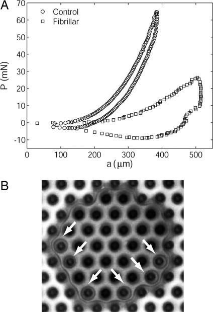
Fig. 5.
Contact pinning and a consequence. (A) This plot of load P vs. contact radius a for the indentation experiment reveals strong hysteresis in the fibrillar sample due to crack trapping. During retraction, a decreases with P for the control sample, whereas it remains nearly constant until tensile values of P are reached for the fibrillar sample (fibril length = 60 μm, nearest neighbor spacing = 62 μm). The experimental geometry is shown in Fig. 3 Inset. (B) Fig. 3F shown at larger magnification. Note that interfacial cavitation occurs under several fibrils ahead of the pinned crack tip as the indenter is retracted. Cavities are indicated by arrows. Nucleation of voids indicates a large tensile stress in front of the crack tip, a situation that occurs when the crack tip is pinned between fibrils while the external load continues to increase.

