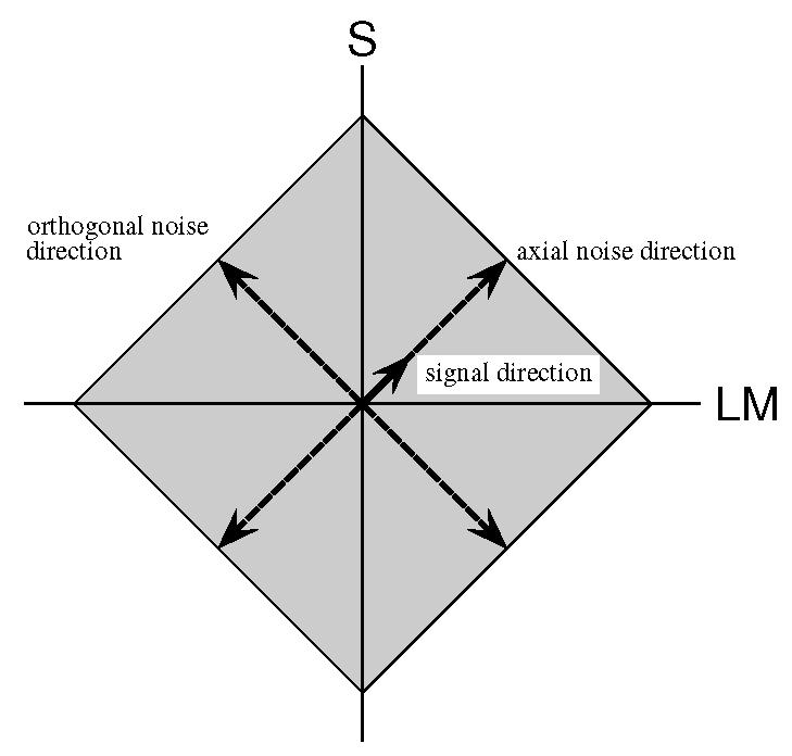
Figure 1.

A schematic representation of the stimulus in the equiluminant plane. All stimuli are defined with respect to the LM and S axes. The signal is indicated by the short solid arrow. The masking noise is composed of two independent, uniform noise components, one axial with the signal and the other orthogonal. The grey diamond indicates the region over which the noise may vary. To represent a signal in a different direction, the diagram would be rotated.
