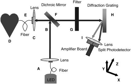
FIGURE 1.
Schematic diagram of the fiber-based ratiometric optical channel. The labels A–D refer to the illumination pathway of the channel as described in the text. All lenses have a radius of 5 mm. The dichroic mirror and filter are 25 mm × 25 mm × 1 mm. The diffraction grating is 25 mm × 25 mm × 9.5 mm. The labels E–I refer to the detection pathway of the channel as described in the text. The xyz directions are also shown. The y direction is perpendicular to the xz image plane.

