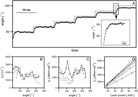
FIGURE 4.
Calibration of the angular trap stiffness for 500-nm nonrotating bead pairs attached to F1 molecules. (A) Bead-pair angle, θbp (black), and trap angle, θt (gray), versus time for a bead pair in a trap moving in 10° steps without feedback. Angles are averages over 40 successive rotations. (Inset) Step-response, with exponential fit. (B) The ratio of angular trap stiffness to rotational viscous drag coefficient, derived from the time constants in the fits in panel A as described in the text, versus angle, for three bead pairs on HRP surface (black) and silane surface (gray) (Methods). (C) Angular trap stiffness versus angle for the same bead pair as in panel B (black) and two additional bead pairs (gray) on silane surface. (D) Trap stiffness using at 45° versus laser power for several bead pairs on a BSA surface (Methods). Data were sampled at 10 kHz, laser power in panels A–D was 30 mW, and the trap was kept on 0.42 μm radius circle. Bead pairs with φ ∼ 90°, which performed free rotational Brownian motion without the trap were chosen for all calibration experiments. Error bars in B and C are standard errors obtained by averaging values of ratio of angular trap stiffness to rotational viscous drag coefficient and angular trap stiffness of two adjacent angles.

