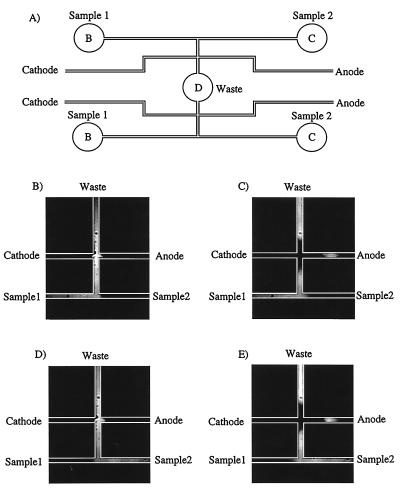
Figure 2.
(A) Layout of the sample injector. The sample injector includes four sample reservoirs, two separation columns, and one common waste reservoir, labeled as in Fig. 1. (B–E) Fluorescence images illustrating the operation of the injector with fluorescein.

