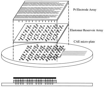
Figure 3.
Schematic of the elastomer reservoir array and electrode array loading assembly. The elastomer loading array is placed on top of the microplate so that the holes in the elastomer are aligned with the drilled holes in the CAE microplate. The electrode array is then placed on top of the elastomer to address the reservoirs.

