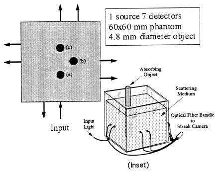
Figure 1.

A scheme of experimental arrangement of source detector pairs. An absorber was placed at three locations (a, b, and c) inside medium that was 10 mm away from the center of the square. Each fiber pair was 1.25 cm apart, with one at the center of the wall. Inset shows a three-dimensional schematic diagram of the arrangement. [Reprinted with permission from ref. 9 (Copyright 1996, Optical Society of America).]
