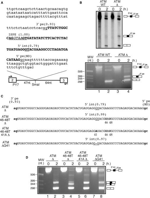
Figure 1.
(A) A schematic diagram of the ATM WT construct. White boxes represent tropomyosin exons 2 and 3 whilst the single line represents the intron. The arrows indicate the primers used for the RT-PCR analyses of the processed RNA templates. The ATM intronic region is in small letters whilst pseudoexon sequences are in bold capital letters. The ISPE sequence is underlined and the GTAA nucleotides deleted in the ATM Δ construct are in italic. Within the ATM sequence all potential donor and acceptor splice-site sequences together with their scores calculated according to the NNSplice program are underlined (ND indicates that the splice site is not detected as a viable donor site by the program). It should be noted that although the ISPE sequence scores very well as a potential donor site it is never used by the splicing machinery. (B) In vitro splicing analysis of the ATM WT and ATM Δ RNAs both using radioactive templates (upper panel) and by RT-PCR (lower panel). In order to investigate 5′int/5′pe donor-site usage a number of mutants were engineered in the ATM Δ construct (C shows a schematic diagram). In mutant ATM 46-48T Δ the 46A and 48G nucleotides were replaced by a T in the ATM Δ context. This improved 5′int donor site was then inactivated by introducing an A for a G substitution in position 41 (mutant ATM 46-48T 41A Δ). Cryptic 5′int donor-site improvement was also obtained by deleting the G in position 41 (mutant ATM Δ G41). (D) In vitro splicing analysis of these mutants.

