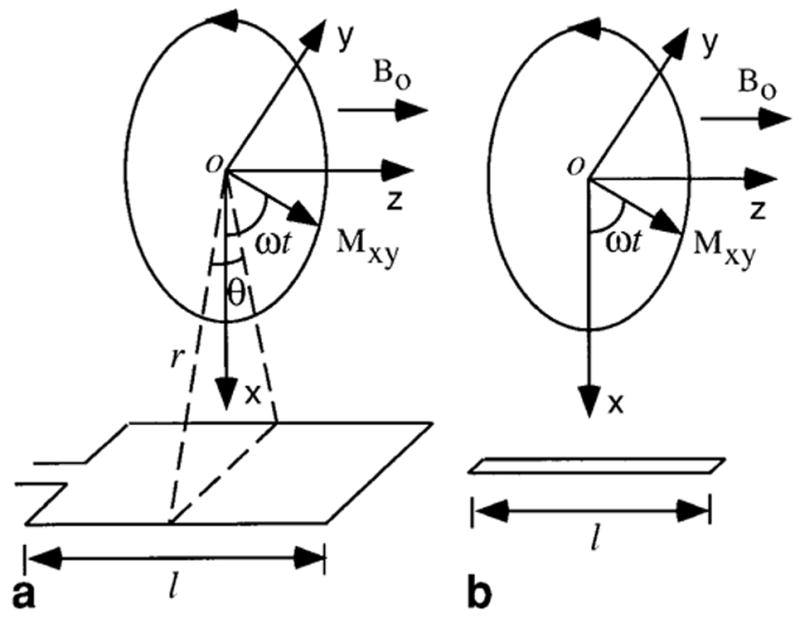
FIG. 1.

MRI signal detection by (a) loop and (b) linear antennas. Here z is the longitudinal direction that is parallel to the static magnetic field B0. The x-y plane is the transverse plane in which the transverse magnetization Mxy(r), originated at point O, rotates with frequency ω to generate a time-varying magnetic field B. In part a a loop antenna is used to detect B. The angle θ is the view angle from the point O. This angle provides the measure of how close the two sides of the loop are. In part b a linear antenna is used to detect B. The distance between point O and the linear antenna is r.
