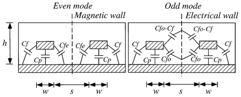
FIG. 14.

End elevation sketch of the PSA showing the distributed capacitance for even (left) and odd (right) modes of a pair of coupled strips. The vertical dashed lines indicate magnetic and electric “walls” where the magnetic and electric fields are zero (virtual ground for the electric field).
