
Fig. 5.
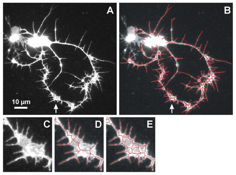
Skeletonization of a neurite region with non-uniform fluorescent signal. (A) Anti-HRP image of a neuron with regions of broad, non-uniform signal (e.g., arrow). (B) Skeleton (red), obtained using the non-uniform signal mode, superimposed after thickening to three pixels to improve visibility. (C–E) Enlargement of a region, marked by arrow in panels A and B, which has non-uniform signal. For comparison, see Fig. 1D which shows an enlarged broad region with uniform signal. (C) Fluorescent image. (D) Overlay of the skeleton (one pixel wide) created using non-uniform signal mode, which results in the desired representation of neurite branching. (E) If uniform signal mode is used, the resulting skeleton encloses the darker gray sub-regions instead of traversing them, which would cause spurious length and branch number computations.