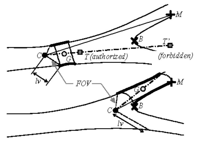
Fig. 5.

Displacement process: the bold contours represent the 3D surface points used for the computation of the displacement direction (C: optical center or virtual sensor position, CM: viewing direction, CG: displacement direction, T: local target point).
