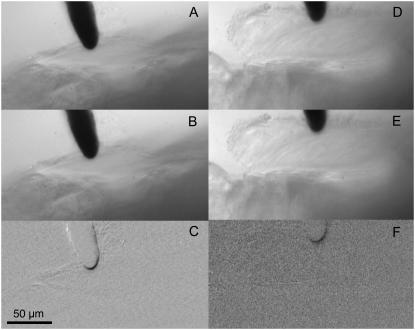
FIGURE 5.
Sensor indentation shown for a basal- and a middle-turn location. (A–C) Images for a basal-turn location. (D–F) Images for a middle-turn location. (Upper and middle) Different sensor indentations. (Lower) Subtracted images of the indentations shown in A and B (C) and D and E (F). Regions that exhibit displacement show up as darkened areas in C and F.

