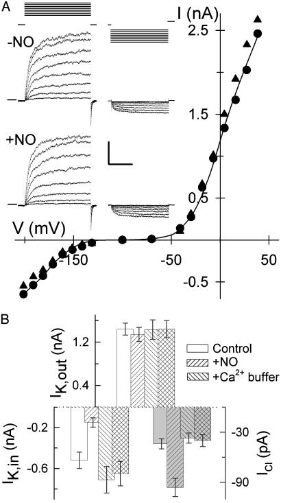
Fig. 3.
Ca2+ buffering blocks NO inactivation of IK,in and activation of ICl. (A) Voltage-clamp recordings from an intact Vicia guard cell impaled and buffer-loaded from a microelectrode containing 50 mM 1,2-bis(2-aminophenoxy)ethane-N,N,N′,N′-tetraacetate (BAPTA). Shown are steady-state current–voltage curves determined from voltage-clamp steps (Inset) before (•) and after 6 min of exposure to 10 μM SNAP (▴) as described for Fig. 1. Data for IK,in and IK,out fitted jointly (solid lines) to common Boltzmann functions (see Fig. 1) gave half-maximal conductance for IK,in of -178 ± 3mV(-NO) and -181 ± 4mV(+NO). (Inset) Current traces for IK,out (Left) and IK,in (Right) before (Middle) and during (Bottom) NO treatment. Zero current is indicated on the left. Voltage protocols (Top) of steps between -200 mV and +50mV from holding voltage of -100 mV. (Scale: horizontal, 2 s; vertical, 1 nA.) (B) Summary of IK,out, IK,in, and ICl (shaded bars) before and after exposure to 10 μM SNAP with (n = 10) and without (n = 27) 50 mM EGTA or 50 mM BAPTA loading. Currents were determined as described for Figs. 1 and 2.

