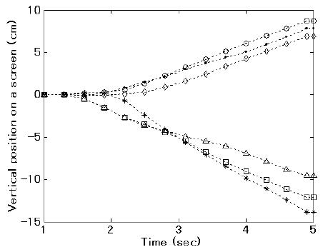
Fig. 4.

An example of cursor orbit by using the present method for subject #1. Horizontal axis is time during a trial. The vertical axis corresponds to a width of a screen. These 6 orbits of a cursor were results of correct case in the test data. The upper three orbits refer to left-hand motor imagery. The lower three orbits refer to right-hand motor imagery. Subject #2 had a similar cursor control trajectory.
